Banks, D and Birks, D., Heat from the Ground. Geoscientist 30 (2), 12-17, 2020
https://doi.org/doi: 10.1144/geosci2020-070, Download the pdf here
Ground Source Heat (GSH) exchange has been heralded as part of the solution to reducing UK carbon emissions. David Banks and David Birks urge tempering optimism with a degree of caution.
Amidst the growing international consensus of an imminent carbon emergency, there is a pressing need for all nations to reduce their carbon emissions quickly and significantly. In the UK, heating accounts for nearly half of all energy usage (DECC, 2011) and has thus become a national priority for carbon reduction, but easy strategies for achieving this have proved elusive (BEIS, 2018). Electrically-powered heat pumps “hoovering up” low temperature heat (e.g. in the range 0 – 15°C) from the ground beneath our feet, or from air, sea or rivers, are arguably the most promising technology, and two decades of GSH implementation across the UK have seen some remarkable successes and rapid accumulation of experience. Nevertheless, there remain significant flaws in the procurement, implementation and especially the management, monitoring and aftercare of such systems.
Decarbonising the electricity grid
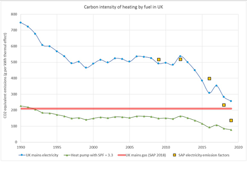 Figure 1: A plot of the carbon intensity of UK electricity, compared with mains gas, for heating, based on government statistics. The lowermost curve shows the carbon intensity of heat delivered by an electrically powered heat pump with a seasonal performance factor (SPF) of 3.3: these are now considerably more carbon efficient than mains gas boilers. SAP = Standard Assessment Protocol (BRE, 2019).
In recent years, well-performing heat pump systems have become significantly more carbon efficient than mains gas boilers; a trend likely to continue as the electricity grid becomes progressively decarbonised (Figure 1). Such heat pumps use modest amounts of electricity to transfer environmental heat – from, for example, the ground - to a building, rather than simply converting electrical energy to heat energy, as conventional electrical resistance heaters do. Moreover, heat pumps can run in the opposite ‘direction’; providing air conditioning by transferring surplus summer heat from a building to the ground, where it can be stored until winter, given the right geological conditions.
Geologists, and especially hydrogeologists, have much to contribute to this field of low temperature GSH, or thermogeology. However, geology alone is not enough - we need to be able to communicate meaningfully with buildings services and heating, ventilation and air conditioning (HVAC) engineers to deliver effective heating and cooling systems. We need to get to grips with the science and engineering of designing both:
- closed loop borehole systems, where a heat transfer fluid is circulated around an array of underground heat exchangers, extracting and carrying a cargo of heat back to a heat pump (Figure 2). While such systems benefit from favourable geological conditions (easily drillable rock with high thermal conductivity, such as sandstones or granite), they can be constructed and function well in a very wide range of geological conditions, including unconsolidated deposits, such as clays and silts. British closed loop boreholes are typically 50-150 m deep, but can be deeper or shallower.
- and open loop well doublets, where natural groundwater is pumped from an abstraction well, through a heat exchanger or heat pump, back to the aquifer via a re-injection well (Figure 2). These systems rely on favourable geology: the presence of a good aquifer, relatively shallow groundwater levels (to avoid excessive pumping costs) and a suitable groundwater quality. The wells’ depths depend on the depth of the aquifer – they can be anything from 10 to several hundred metres deep, but in the UK are often 50 - 150m.
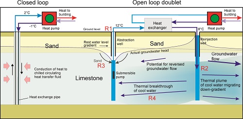 Figure 2: Indicative diagram of a closed-loop borehole system (left) and a groundwater-based open-loop well-doublet heat pump system (right). R1-R4 illustrate the locations of the key risks discussed in the article. © David Banks.
Neither of these systems suffers from any fundamental theoretical flaw. Experiences from nations where GSH practice is several decades more advanced than the UK (e.g. Sweden) testify to the fact that subsurface heat exchange can work very well. Indeed, the Swedes (arguably because they have never enjoyed cheap, plentiful fossil fuels) tend to think about thermal fluxes and environmental sources, stores and sinks of heat in a way that does not come naturally to most British engineers.
However, in the UK, both system types are vulnerable to poor practice at the procurement, construction and management stages.
Closed loop systems
In 2010, GSH practitioners were rudely awakened by an Energy Saving Trust report (Roy, et al., 2010) suggesting that a significant number of closed loop systems were underperforming and not delivering the cost and carbon savings that were promised. Several factors were at play, some of which were improved by minor interventions (Energy Saving Trust, 2013). Among these factors were excessive heating delivery temperatures, user behaviour and poor hydraulic design.
In other cases, it seems that subsurface heat exchangers may have been under-designed (Dunbabin & Wickins, 2012). A closed loop geothermal system needs a certain amount of buried downhole heat exchanger to extract a certain quantity of heat. If insufficient heat exchange pipe is present, the system may still work, but will run less efficiently. This, together with the fact that customers do not fully understand the complex interplay of hydraulic and thermal processes involved, yet still adopt a competitive tendering process, is an invitation to cut corners on design. Would you, as a client, purchase a 30-borehole scheme which will ‘work’ rather than a 36-borehole scheme that has a 20% greater capital cost but which will be more efficient?
An important distinction between closed and open loop systems is that closed loop systems require considerably more subsurface installation to achieve the same heat yield. For example, a notional 100 kWth closed loop system may require several thousand metres of subsurface heat exchanger and a pipe network with several hundred joints, each representing a possible point of failure. We’re aware of a small number of large commercial closed loop systems with issues of leakage of thermal transfer fluid, resulting in poor performance, increased cost and potential environmental liability. It remains to be seen whether these are isolated incidents or symptomatic of a wider problem, resulting from poor practice at the procurement, construction and management stages.
It is encouraging that British GSH installers have taken steps to self-regulate. The Ground Source Heat Pump Association has now developed standards for closed loop systems (GSHPA, 2011), including recommendations for quality of joints and pressure testing. The Microgeneration Certification Scheme has published sets of tables outlining the expected lengths of borehole heat exchanger required for given heat loads (MCS, 2011). While not universally applicable, such standards do at least provide a level playing field for reputable contractors and provide the customer with some form of transparent means to verify designs.
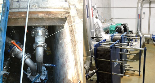 Figure 3: Two components of an open loop ground source heat system: (left) a water well - in this case installed with a submersible pump and reinjection main capable of abstracting/recharging up to 20 L/s (photo © David Birks) and (right) two plate heat exchangers (photo © David Banks)
Open loop systems
Because closed loop systems typically require a lot of drilling (100 kWth of heat extraction may require at least 25 boreholes to 100 m depth), the open loop doublet option has become increasingly popular. Rather than relying on thermal conduction for heat transfer in the ground, an open loop system actively pumps groundwater from the ground, along with its convected cargo of heat. A simple open loop system comprises an abstraction well and pump, from where the groundwater is conveyed to a heat exchanger (Figure 3). At the heat exchanger, heat is either removed (with the aid of a heat pump) or rejected to the water flow. The groundwater is then typically returned to the aquifer via a reinjection well, meaning that it is conserved for higher-value uses, such as potable water supply. The removal of, say, 4°C of heat from a pumped groundwater flow of 6 L/s is equivalent to extraction of
6 L/s x 4 °C x 4.19 kJ/°C/L = 101 kJ/s or 101 kWth of heat (a kWth is a kilowatt, or kilojoule per second, of thermal energy. A small house may require around 6 kWth heating in winter.)
Thus, an open loop system based on two wells, shifting 6 L/s of groundwater, can supply as much heat as 25 closed loop boreholes. It’s not surprising that such open-loop systems have become increasingly popular, especially in cities underlain by productive aquifers, such as London. But there are risks involved and these need to be managed.
David Birks and his colleagues (Birks, et al., 2015) identified four principle geoscience performance indicators (or risk factors) to be documented on handover of this type of system, forming a baseline against which later performance can be monitored:
- Risk R1: Decline in borehole productivity.
- Risk R2: Decline in borehole injectivity.
- Risk R3: Pumping of particulates from aquifer.
- Risk R4: Progressive change in abstracted groundwater temperature.
The wells comprising an open loop doublet need to be properly constructed water wells; and it is not invariably the case that the HVAC and ground source heat engineers (or the drillers they employ) have sufficient experience of the local aquifers to construct durable, efficient wells.
Over our careers, we have watched some open loop systems succeed and continue to satisfy clients’ heating needs. But we have also seen many fail - and have reluctantly come to the conclusion that groundwater-based open-loop ground source systems are not low maintenance heating and cooling solutions. On the contrary, they require the operator to take an active interest in monitoring the performance of the wells, heat pump and heat exchanger and the hydrochemistry of the water. And very few clients (quite reasonably enough) are prepared to do this. They, ultimately, simply want a functioning heating or cooling system that switches on and off in response to demand and which requires minimal maintenance.
As any experienced hydrogeologist or groundwater engineer knows, wells require monitoring and maintenance, and often regular programs of rehabilitation. Water wells suffer from corrosion, pump degradation and failure, chemical clogging, sediment mobilisation and biofouling (Houben & Treskatis, 2007), which may result in long term decline in performance or yield (Risk R1). Almost all of the big water utility companies now recognise this and have implemented rolling programs of monitoring, responsive maintenance and rehabilitation. And what applies to abstraction wells applies also to reinjection wells, but probably doubly or triply so. At least with an abstraction well, the flow of water from formation to well may have some tendency to remove clogging materials. In a reinjection well, the water, with its load of particulate matter, chemical flocs, gas microbubbles and microbes, is being forced into the well screen, gravel pack (if any) and aquifer. Small wonder that it is accepted lore that reinjection wells typically perform less well than abstraction wells, will likely require routine maintenance and rehabilitation and may have a finite life (Risk R2). A recent academic study (Birks, 2019) undertook a multi-year monitoring of the performance of two groundwater-based heating/cooling systems in Central London, the results of which are presented in Figures 4 and 5, showing that regular observation can reveal declining well performance.
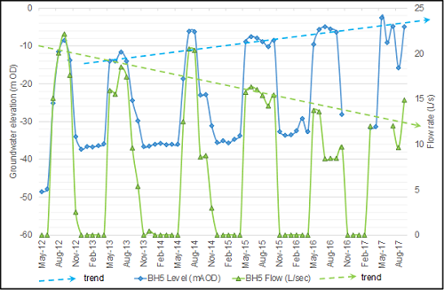 Figure 4: Monitoring of groundwater level and reinjection rate in a reinjection well in a Central London open-loop scheme. Flows (green) show a declining trend, while water levels (blue) rise, suggestive of progressive clogging.
Design and monitoring
The potential for clogging and declining performance of reinjection wells can be enormous. Some particulate aquifers (sand and sandstones) anecdotally seem more prone to it than fissured limestone aquifers such as the Cretaceous Chalk of south-east England. Clogging can result from:
- particles (turbidity) in the water being reinjected into an aquifer.
- rearrangement of fine particles in the aquifer itself or gravel pack.
- precipitation of minerals on and in the well’s walls. Iron and manganese oxyhydroxides, formed when dissolved Fe++ and Mn++ ions are exposed to oxygen, are particularly troublesome.
- growth of bacterial biofilms on and in well walls. Iron bacteria such as Gallionella are notorious.
- small bubbles of dissolved gas, exsolving from water due to pressure release or under-pressure in a reinjection well system, being forced into an aquifer matrix and lodging there.
Several text books (Bloetscher, et al., 2005; Pyne, 1994; Misstear, et al., 2017) are available to provide advice on these issues. But good design is only part of the story. Well doublet systems need regular monitoring of water levels, temperatures and flows. And collected data must not just sit in a logger or a hard drive. It needs to be regularly analysed by an experienced hydrogeologist to spot signs of deteriorating performance. If these signs are spotted, prompt action may be required – for example, iron oxyhydroxide slimes tend to harden over time if left untreated, evolving into progressively harder and more crystalline forms: goethite and ultimately something resembling haematite. Some conditions can be controlled by routine maintenance: regular back-pumping of reinjection boreholes to remove particulate matter from well walls; routine disinfection of wells to control bacterial growth; even dosing with reducing agents has been suggested to minimise iron and manganese deposits. Occasionally, more decisive intervention may be required: acid / disinfectant treatments or high-pressure jetting.
Poorly designed water wells may tend to pump sediment particles along with groundwater (Risk R3). As well as fouling heat exchangers and injection wells, sediment pumping can cause ground movement. 6 L/s of water, with 2 mg/L sediment, equates to the removal of almost 0.4 tonnes of geology per year!
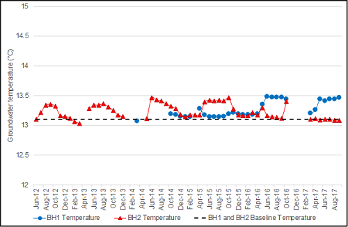 Figure 5: Monitoring of groundwater temperatures in two abstraction wells in an open loop system in Central London, over a six-year period, where the cumulative net heat input to the ground was approximately 1,800,000 kWh. The data show small annual cycles in temperature (rises following reinjection of waste summer heat), but little sign of any long-term trend.
A finite capacity
We should remember also that the ground is not some ‘infinite black hole’ in its thermal behaviour. It has a very large, but ultimately finite, capacity to yield or store heat. While small GSH systems can usually rely on sustainable extraction of heating or cooling, large scale schemes need much more careful consideration of the subsurface thermal heat balance. For example, an open loop doublet where the wells are too closely spaced may suffer from ‘thermal feedback’ and a tendency for the temperature of the abstracted water to change (Risk R4). If a lot of open loop systems are constructed within a small area, all extracting heat from (or, more likely, rejecting heat to) groundwater, the temperature of the aquifer may change. There are already signs that this may be happening in Central London, with some observed warming trends (Figure 6). Happily, the Environment Agency is monitoring the situation, although their powers to regulate it are somewhat hindered by heat / the absence of heat not being conventional contaminants that the law has evolved to regulate. It is problematic to construe heat as a polluting ‘substance’.
In large-scale GSH systems (open- or closed-loop, and especially those constructed within a small property footprint) it is desirable to attempt to balance heating and cooling (heat rejection) fluxes over an annual cycle, thus using the ground more as a thermal ‘store’ or ‘battery’ than as merely a heat source or sink.
A gap in the market?
The Chartered Institution of Building Services Engineers (CIBSE) has recently published a readable and highly informative guide to open loop groundwater-based heat pumps (CIBSE, 2019). Even in this publication, we feel that the risks associated with groundwater wells, and reinjection wells in particular, are not given the emphasis they deserve. Such risks are often manageable by professional water utilities companies, who routinely monitor supply boreholes for efficiency and signs of deterioration. Such risks are not manageable by a typical heating and cooling customer (a school, large office, community building or block of apartments), who simply want ‘heating or cooling at the flick of a switch’ and who have neither the experience of groundwater engineering nor the interest to run a water well doublet. We should not expect such clients to be aware of risks associated with well clogging or thermal feedback, still less to implement remedial interventions.
Clients have commented to us that it has been difficult to find a one-stop shop – a responsible contractor who can undertake to monitor, interrogate and maintain such groundwater-based heating systems. This is surely an obvious gap in the market, which should be filled by qualified groundwater engineers, supported by hydrochemists and hydrogeologists. Any handover procedure for a groundwater-sourced heat pump scheme should include the establishment of a contract for the aftercare of a completed groundwater heating/cooling well doublet, aligned to both performance and durability.
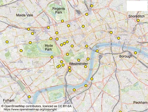
Figure 6: Locations of open loop ground-source heating / cooling systems in London as of 2018. Based on data provided in (Environment Agency, 2018)
An elephant in the room
The drive to decarbonise the UK’s energy supply finally appears to have gained traction amongst the public, politicians and industry. However, public consciousness often focuses on decarbonising electricity and transport, while the decarbonisation of heat remains an ‘elephant in the room’. Environmental heat pumps in general, and ground source heat exchange in particular, will undoubtedly have a role to play in the heat revolution. If they are to succeed, geologists need to focus less on the ground as simply a source of heat and more on efficiently communicating with engineers to enable the subsurface to form a component of district-wide heating and cooling systems, incorporating sinks, sources and stores of heat. Practitioners need to step up their customer aftercare when it comes to monitoring and maintenance of existing GSH systems.
Authors
David Banks, Holymoor Consultancy Ltd., Chesterfield, UK, also Senior Research Fellow at Glasgow University.
David Birks, WSP Ltd., Bristol, UK.
References
BEIS, 2018. The clean growth strategy. Leading the way to a low carbon future, s.l.: UK Department for Business, Energy and Industrial Strategy.
Birks, D., 2019. Groundwater heating and cooling - an evaluation of resilience in the context of recharge and temperature. PhD thesis, s.l.: s.n.
Birks, D., Coutts, C., Younger, P. & Parkin, G., 2015. Development of a groundwater heating and cooling scheme in a Permo-Triassic sandstone aquifer in South-West England and approach to managing risks. Proceedings of the Ussher Society; Geoscience in South-West England, 13(4), pp. 428-436.
Bloetscher, F., Muniz, A. & Witt, G., 2005. Groundwater injection: modeling, risks, and regulations. New York, USA: McGraw Hill.
BRE, 2019. The Government’s Standard Assessment Procedure for energy rating of dwellings. Version 10.1, Watford, UK: Buildings Research Establishment on behalf of BEIS.
CIBSE, 2019. CP3 : Open-loop groundwater source heat pumps: CoP for the UK, London, UK: s.n.
DECC, 2011. Renewable heat incentive, s.l.: UK Department of Energy and Climate Change.
Dunbabin, P. & Wickins, C., 2012. Detailed analysis from the first phase of the Energy Saving Trust’s heat pump field trial. Evidence to support the revision of the MCS Installer Standard MIS 3005 Issue 3.1, London, UK: The Energy Saving Trust / Department of Energy and Climate Change.
Energy Saving Trust, 2013. The heat is on: heat pump field trials phase 2, London, UK: The Energy Saving Trust.
Environment Agency, 2018. Management of the London Basin chalk aquifer - Status report 2018, s.l.: s.n.
GSHPA, 2011. Closed loop vertical borehole design, installation & materials standards – Issue 1.0, Milton Keynes, UK: UK Ground Source Heat Pump Association.
Houben, G. & Treskatis, C., 2007. Water Well Rehabilitation and Reconstruction. s.l.:McGraw-Hill Professional.
MCS, 2011. MCS 022: Ground heat exchanger look-up tables. Supplementary material to MIS 3005. Issue 1.0. Microgeneration Installation Standard, London, UK: Microgeneration Certification Scheme. Department of Energy and Climate Change Misstear, B., Banks, D. & Clark, L., 2017. Water wells and boreholes. 2nd edition. s.l.:Wiley-Blackwell.
Pyne, R., 1994. Groundwater recharge and wells: a guide to aquifer storage recovery. Boca Raton, Florida, USA: Lewis / CRC.
Roy, R., Caird, S. & Potter, S., 2010. Getting warmer: a field trial of heat pumps, London: The Energy Saving Trust.