 Geological conditions and anthropogenic legacy will significantly affect HS2 in mid-Cheshire, say Chris Eccles and Simon Ferley.
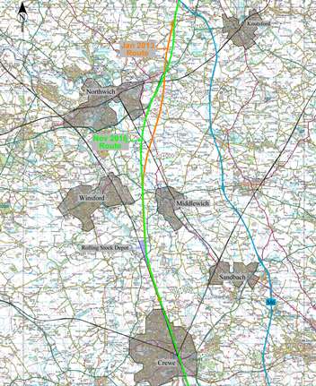
This 20km section of the HS2 Phase 2B route passes through gently undulating farmland crossing a number of A-roads, canals and two minor railway lines that would, in many areas of lowland UK, have routine ground engineering risks. However, this part of the HS2 route will be technically challenging for design and construction, due to the presence of deep salt karst and several hundred years of human impact on the ground - including below-ground infrastructure. In November 2016, HS2 announced a change in both horizontal and vertical alignments through Cheshire, as a result of both these factors.
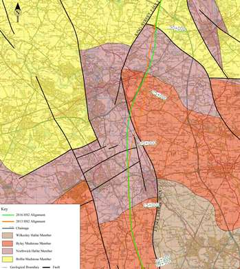
Image right: HS2 Alignment in Mid-Cheshire: 2013 (orange) 2016 (green)
HS2 Alignment
HS2’s alignment through Cheshire was first published in January 2013 and revised in November 2016. This revision involved moving the track, in an area southwest of Northwich, up to 800m west because of geology and subsurface anthropogenic features.
The route leaves the Crewe to Preston line north of Crewe, passing between Winsford and Middlewich, crossing the A530 King Street SE of Northwich and then running east of Northwich entirely through farmland (and close to a number of villages).
The 20.2km length of the 2016 route covered here is from HS2 Chainage 9.9km to 30.1km, and includes two Rail Crossings, 11 River/Canal crossings, 10 Road Crossings, re-routing 2.3km of dual carriageway, embankments up to 26m high and a large rolling-stock depot. There are no cuttings.
|
Table: Nomenclature & Classification of Triassic Strata in the Cheshire Saltfield
|
|
Group
|
Old Formation Name
|
New Formation Name
|
Typical Lithology in the Saltfield
|
|
Mercia Mudstone Group
(Formerly Keuper Series)
|
Upper Keuper Marl
|
Brooks Mill Mudstone Formation
|
Red-brown mudstone gypsum/anhydrite nodules and a bed of anhydrite
|
|
Upper Keuper Saliferous Beds
|
Wilkesley Halite Formation
|
Thick rocksalt (halite) with red-brown blocky mudstones
|
|
Middle Keuper Marl
|
Wych Mudstone Formation
|
Blocky mudstone with gypsum/anhydrite nodules and thin rocksalt bands in the base
|
|
Byley Mudstone Formation
|
Poorly laminated and blocky red-brown mudstone
|
|
Lower Keuper Saliferous Beds
|
Northwich Halite Formation
|
Rocksalt with thin laminated mudstones
|
|
Lower Keuper Marl
|
Bollin Mudstone Formation
|
Interlaminated red-brown and green-grey mudstones with some thin dolomitic siltstone laminae, with thin veins of gypsum
|
|
Keuper Waterstones
|
Tarporley Siltstone Formation
|
Interlaminated and interbedded red-brown with green-grey mottled siltstones, mudstones and sandstones
|
|
Sherwood Sandstone Group
(Formerly Bunter Series)
|
Lower Keuper Sandstone (LKS)
|
Helsby Sandstone Formation (HEY)
|
Sandstone with pebble beds and siltstone
|
Geology
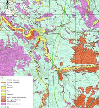
Superficial deposits in this part of Cheshire are up to 30m thick. Drift deposits at surface are nearly all glacial till, with alluvium in the river valleys. Almost no glacial sand and gravel or fluvioglacial deposits are mapped below this part of the route.
The bedrock consists of the Mercia Mudstone Group (formerly Keuper Series, see Table) over 1.5km thick. The subdivision underlying the whole of this area is the Sidmouth Mudstone Formation, which includes major deposits of halite (rock salt) of economic importance - especially the Northwich Halite. This is a series of halite strata interbedded with marl (overall, the Northwich Halite is 75% salt 25% marl). This member is 200 to 285m thick and thins east to west.
The route runs through the north of the Cheshire Basin Syncline with strata dipping south. There is a single major fault (the King Street fault, crossed at Chainage 22.5km) forming a curved line running roughly north-south through Cheshire. The relative movement across the fault is a relative drop of over 500m to the east.
Halite
Salt extraction in Cheshire has a long history stretching almost continuously over 2000 years with small scale Roman and mediaeval saltworks from brine springs. In 1670, John Jackson, digging for coal in Marbury (three miles north of Northwich), found salt. From then until 1928, mining continued in Northwich in Witton, Dunkirk, Marbury & Marston areas. The oldest mine still working is Compass Minerals’ Winsford mine, operating since 1844.
Pumping of brine from wells sunk into wet rockhead (‘wild brine pumping’) started in the 1800s and continued until 2006. This often caused subsidence many miles away - due to hydrogeological conditions, groundwater was not drawn in uniformly, with flow following so-called ‘brine runs’. The most active subsidence often took place where relatively salt-free water was drawn towards a well and met bedrock halite.
 Pumping from flooded conventional mines was carried out, but the practice was banned in1938 due the scale of subsidence. Such so-called ‘bastard brine pumping’ created extensive subsidence lakes or ‘flashes’, particularly north of Northwich. Controlled solution mining in Cheshire began in 1928 and this is the method currently used to withdraw salt for the county’s chemical industry.
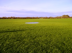
Image right: Subsidence feature. Photo: Chris Eccles
Materials of many kinds are also stored in the salt caverns, including documents (Winsford), hazardous waste (Winsford), solvent waste (Holford), strategic oil reserves (currently being decommissioned) and gas. Construction of gas-storage caverns began in 2006, becoming operational in 2011. Four of these lie close to the proposed route.
Wet rockhead
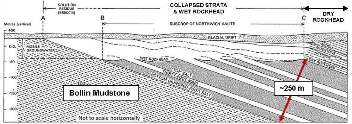
Where salt-bearing rocks of the Northwich Halite occur at rockhead, it is referred to as ‘wet rockhead’, indicating that saturated brine is present (from dissolution of the upper section of the halite) and that original brine extraction has taken place. In contrast, the traditional name for an area where salt has not dissolved (because it is sealed beneath a cover of the Byley/Wych Mudstone) is ‘dry rockhead’ (‘dry’ here meaning simply that water is not dissolving salt). Wet rockhead is present below about 57% of the route covered here.
Image right: Section showing Wet & Dry Rockhead (From BGS Memoir Sheet 109 Earp J R and Taylor B J 1986 Memoir: BGS Sheet 109
Geology of the country around Chester and Winsford. British Geological Survey).
At ‘wet’ rockhead, groundwater has circulated, dissolving out the salt from the strata and leaving only the interbedded insoluble marl. As salt dissolves, the marls collapse and become broken up (brecciated) and softened. Large voids from six to 10 metres high can be found in the brecciated/collapsed strata, although large ‘rafts’ of intact marl also occur. The overall thickness of brecciated ground typically varies from 15 to 120m below drift. It can be difficult to distinguish between glacial deposits and brecciated bedrock because both have similar composition.
 The development of collapsed strata was strongly influenced by groundwater flow and the modification of the groundwater regime during the last (Devensian, and possibly earlier) glaciations. The Devensian glaciation buried Cheshire in a thick ice-sheet with water at its base, raising groundwater pressures and flushing out saline waters from the ground, forcing fresh salt-free water to the dissolution surface of the salt and cutting deeper into the sequence. When the ice melted, further dissolution of the salt occurred as new regional groundwater patterns formed. Because of glaciations, salt dissolution is now found at up to 120m down.
Image, left: Drift geology map (Map Sheets 97, 98, 109 & 110, British Geological Survey © NERC BGS)
Cavities
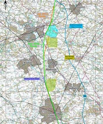
Solution-mining of the Northwich Halite at depth has taken place in areas of dry rockhead for the last 79 years, and continues today. The 2013 proposed route passed through 1.46km of the Holford Brinefield east of Lostock Green, passing over 14 brine cavities. Here, 20m of drift lie over Byley and Wych Mudstones, with solution mining in the underlying Northwich Halite. Cavities may be up to 170m across and are as little as 30m (or less!) apart, the shallowest being only 60m below surface (in the north of the brinefield). Some cavities at Holford are being used to store solvent waste.
In a number of locations at Holford there has been break-through between adjacent cavities. In Cheshire, no solution-mined cavities have collapsed; but near Preesall in Lancashire similar solution mining was carried out in the Northwich Halite to shallower depth, resulting in a series of collapses that created lakes.
It is the nature of rock salt to creep over time, and the ground above the Holford Brinefield is slowly settling by three or four millimetres a year. The settlement bowl extends to a wider area than the actual plan extent of the cavities.
 To the south of the Holford Brinefield the halite is deeper and the 2013 route passed over gas-storage caverns. The presence of such caverns presents a lower risk than the Holford Brinefield, because the crown of the gas caverns is usually deeper than 600m. Individual storage caverns may be 100m across and over 100m high. Locating HS2 directly over such a cavern is technically possible; but it would affect the surface Control of Major Accident Hazards (COMAH)-regulated infrastructure. The UK Government classifies these gas storage facilities in Cheshire as “nationally strategic.”
Image, right: Solid geology (Map Sheets 97, 98, 109 & 110, British Geological Survey © NERC BGS)
Both 2013 and 2016 routes avoid the EDF gas storage facility of Warmingham between Crewe & Middlewich. The 2013 route crossed both Storenergy’s Stublach Gas Storage facility (south west of Northwich) and the King Street Energy facility, which has planning permission for a new storage field.
Between 2013 and 2016 HS2 carried out a review of the risk from constructing the route across the solution-mined brine caverns at Holford Brinefield and reassessed the importance of the gas storage caverns to the south. Moving the 2016 route to the west avoids both Holford Brinefield and the gas storage caverns. However, it does cross surface facilities for the planned King Street Energy Storage Facility, and intersects the edge of the settlement bowl of the Holford Brinefield.
Salt subsidence
As already mentioned, areas of wet rockhead comprise 54% of the 20.1 km length of the 2016 route. Natural subsidence can occur here in a number of ways.
 Groundwater, flowing at rockhead in depressions, causes slow dissolution. This occurs faster along river valleys. Areas of wet rockhead can often appear stable for long periods, but solution may accelerate if conditions change. Where there has been historic uncontrolled wild brine pumping, subsidence features may still be active many years after pumping ceased.
Image left: HS2 Alignment in Mid-Cheshire, showing a number of obstacles
One area of recent reactivation occurs near Lea House Farm (Chainage 15.75km). Here the farmer has reported that the field, level in 1990, now has two parallel settlement troughs up to two metres deep, and subsidence appears to be accelerating. Not far south, at Yew Tree Farm (close to chainage 15.45km) new subsidence hollows can be seen (picture).
Another subsidence feature in open farmland occurs northeast of Northwich, where a pond has formed since 2004 in a new hollow. The cause of subsidence features in areas of wet rockhead remote from historic wild-brine pumping is usually unknown. They could be due to salt dissolution at depth at rockhead (often more than 60m down), and migration of the void. New subsidence features in open farmland usually go uninvestigated.
The Cheshire Brine Board has assessed farmland hollows near Plumley, (about a kilometre east of the HS2 route). Findings did not indicate deep-seated solution, but concluded that uneven drainage and consolidation of heterogeneous drift deposits were probably responsible. However, even subsidence features caused by shallow movement in drift present a significant potential risk to a high speed railway line (with a very low tolerance to settlement).
Wild brine mining
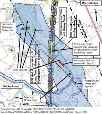 The best known case along the HS2 alignment is at Billinge, between Northwich and Middlewich. The route crosses a 1.5 by 0.5km subsidence trough with a series of six flashes. Here a viaduct will cross both the Northwich to Middlewich railway line and the Trent and Mersey Canal, in an area of wet rockhead with intact salt at about 60m below ground, with collapsed bedrock and glacial deposits above.
Image, right: Area of Subsidence Feature (Shaded Blue)at Billinge Between Chainage 21+000 &
22+000
The Billinge subsidence feature is mentioned in both of the geological memoirs for Geological Map Sheets 109 and 110. These suggest that it is not known whether the subsidence was due to pumping at Northwich (2.5km away) or Middlewich (4km). The location of the subsidence is thought to be partially controlled by the King Street Fault, running parallel to the trough’s eastern edge. Brine pumping will have drawn groundwater principally from just above intact bedrock at the base of previously collapsed strata. Therefore, the already weakened and collapsed strata (formed during glacial periods) underwent an additional period of subsidence when wild brine pumping further reduced strength and increased compressibility, creating c. 60m of highly compressible strata above rockhead.
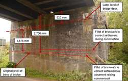
Subsidence in this area has already required the railway embankment to be rebuilt, the canal towpath to be reconstructed, the railway bridge over Whatcroft Lane to be raised by over 2.7m and strengthened.
Winsford salt mine
 Winsford mine is located northeast of Winsford and is owned & operated by Compass Minerals Ltd. An extensive network of caverns lies typically 140 to 220m below ground and extends over an area four by three kilometres in plan. At its northern end, the mine roof is less than 100m down. Mining is by ‘room and pillar’, with caverns up to 20m wide and 8m high. The pillars (of salt) are usually 20m square with a 68 to 75% extraction ratio. Historically, a single bed of salt was mined; but in the last few years Compass have started to mine from a second, shallower level, in the southern part of the mine, directly below the HS2 route, which overall passes over a 3.1km length of workings.
Image, left: Photograph of Southern Face of Northern Abutment of Railway Bridge Over Whatcroft Lane showing fillets and other evidences of subsidence adjustment over time. Photo: Chris Eccles
The 1.16km-long River Dane viaduct, which is up to 26 m high, also runs over the mine. Further to the north a 160m-long viaduct crosses Puddinglake Brook and the Trent & Mersey Canal and is up to 13.4m high. The HS2 route also crosses hazardous waste landfill within the salt mine. The mine sits within in an area of wet rockhead where depth to intact rock decreases from 100m in the south (below Dane viaduct) to 60m (below Puddinglake viaduct). Dane viaduct also runs over an area where mining occurs at two levels; but at Puddinglake viaduct, the depth to the mine is even shallower than in the south - only 30m below intact rockhead.
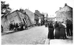
Image, right: Castle Chambers before the building was eventually re-levelled, 1891.
 Due to the thickness of the drift deposits and the collapsed breccia beneath (known to have voids above the mine) foundations for HS2 viaducts are likely to be piled - potentially requiring 120m-deep piles below Dane Viaduct! These will probably be the UK’s deepest on-shore piles and will be particularly difficult to construct. Shorter piles will be required below Puddinglake viaduct, though substantial backfilling and stabilisation work will probably be needed, due to the depth of mining below bedrock.
Drainage & salt karst
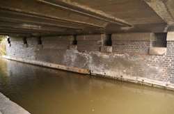 Image, left: Jacking Points in Road Bridge Abutment over Canal. Photo: Chris Eccles
The 2013 route required embankments up to 18m high and cuttings up to 10.2m deep. The 2016 alignment has no cuttings but the embankments are up to 26m high. HS2 said of these changes: “the route has been elevated across the area …... to allow for careful management of drainage and geological risks”. The 2016 alignment recognised that drainage posed a significant potential risk in areas of wet rockhead, particularly deep cuttings, which would act as deep drains and could trigger subsidence. The drainage from embankments located in areas of wet rockhead will have to be carefully managed with ditches and attenuation features, lined to prevent localised infiltration that might lead to subsidence. Remember - in his 2015 Glossop Lecture, Dr Tony Waltham noted how 95% of all karst subsidence are the result of engineering structures interfering with natural drainage!
Innovation
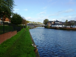 Ground problems have stimulated many innovative solutions in the Northwich area. The use of timber ring-beams for properties enabled them to overcome large scale settlements and then be jacked level again. Many conventional bridges in the area have jacking points for re-levelling. Hayhurst (1898) & Town Bridge (1899) in Northwich (on the Weaver Navigation) were constructed with their turntables on floating pontoons so that as long as the water level is maintained the bridges will continue to remain operational. The construction of HS2 in Cheshire will doubtless require more such innovative solutions to stand alongside these historic achievements.
Image, right: Hayhurst Bridge, a floating swing bridge in Northwich. Photo: Chris Eccles
Authors
* Chris Eccles, Director and Dr Simon Ferley, Technical Director, TerraConsult Ltd
Further reading
Drawings & Reports
- HS2 Drawing No C320-AEC-RT-DPP-220-061002 to 061005: Design Stage Post-Consultation. Preferred Route HSM10B Plan and Profile” Sheets 2 to 5 of 6. Date 11/01/16
- “Salt Related Ground Stability.” Document no.: C601-WAR-GT-REP-220-000001. 61 Pages including appendices. Report is Draft. Date : None on Document. Author Pauline Cooke and checker Dave Wilshaw, both from consultancy Wardell Armstrong.
Geological Maps, Memoirs and British Geological Survey (BGS) Reports
- BGS Map Sheet Runcorn 97 Solid 1:50,000 (1980) and Drift 1:50,000 (1977)
- BGS Map Sheet 98 Stockport Solid 1:50,000 (1977) and Drift 1:50,000 (1962)
- BGS Map Sheet 109 Chester Solid 1:50,000 (1986) and Drift 1:50,000 (1965)
- BGS Map Sheet 110 Macclesfield Solid 1:63,360 (1968) and Drift 1:63,360 (1968)
- Earp J R and Taylor BJ: 1986 :Memoir: BGS Sheet 109 Geology of the country around Chester and Winsford. British Geological Survey
- Evans W B, Wilson A A, Taylor B J and Price D: 1968: Memoir: Institute of Geological Sciences Sheet 110 Geology of the country around Macclesfield, Congleton, Crewe and Middlewich
Papers
- Waltham, T: 2016 : Control the drainage: the gospel accorded to sinkholes. 16th Glossop Lecture, 2015
- Quarterly Journal of Engineering Geology and Hydrogeology, Vol. 49:5-20, first published on February 9, 2016,
- Cooper, A.H. 2002. Halite karst geohazards (natural and man-made) in the United Kingdom. Environmental Geology, Vol. 42, 505-512.