Product has been added to the basket

Third of Forth

Impression

John Brown and Tom Berry* reveal how ground investigations for the proposed Forth Replacement Crossing are redefining the geology of the Firth of Forth.

Geoscientist 21.11 December 2011/January 2012

The Forth Road Bridge opened in 1964, and has deteriorated to such an extent that recent inspections (2005) showed that the main suspension cables of the bridge had suffered significant corrosion, leading to a loss of strength. The Scottish Government concluded that, because replacement or repair of the suspension cables would create an unacceptably high level of disruption, a replacement crossing is required to safeguard this vital artery1.

Picture above: Artist's impression of the new crossing, set against crossings 1 and 2.

Thus, on 15 December 2010, the Scottish Parliament passed a bill for the construction of a Forth Replacement Crossing (FRC)1. The proposed bridge, the third to span the Forth Estuary, will be a cable-stayed bridge structure2.67km long, stretching from a southern abutment west of South Queensferry to its north abutment west of North Queensferry. The crossing will consist of a main bridge of two (650m) spans and two associated backspans supported by three towers, together with southern and northern approach viaducts carrying the bridge deck from the back spans of the main bridge to the abutments. The main contractor for constructing the bridge and connecting roads. Forth Crossing Bridge Constructors (FCBC), was appointed on 18 April 2011. Works are now underway and on track for completion in 20161.

In preparation for a new crossing, Transport Scotland has commissioned several ground investigations across the Firth of Forth in recent years. These have led to a better understanding of the stratigraphy and provided interesting insights into the history of intrusive igneous activity in this part of the Midland Valley of Scotland (MVS).

Fig 1

CROSSING HISTORY


Fig 1 Location Plan (with 250m offset around main crossing structures) indicating the relationship to the existing two bridges.

The narrowing of the Firth of Forth at this location is certainly of historic significance; ferries probably operated here as early as Roman times2. Increased transport demand from pilgrims making their way north to the abbeys of Dunfermline and St Andrews in the 11th & 12th centuries resulted in further development of the crossing and of both North Queensferry and South Queensferry3.

The first fixed crossing - the Forth Bridge – was begun in 1883 and completed seven years later. At the time it was considered one of the greatest engineering feats of civilisation and is still the world’s second longest cantilever bridge2. But the rise of the motor car fuelled demand for a second, vehicular fixed crossing. Construction of the Forth Road Bridge began in 1958 and completed in six years. At that time the new suspension bridge was the longest in Europe3.

The proposed Forth Replacement Crossing, will not only maintain this historically important crossing. It will also complement the other two bridges, in that they illustrate the evolution of bridge design from balanced cantilever, through suspension and finally multi-span cable-stay.

Geol map

MIDLAND VALLEY


Fig 2: Extract of 1:50,000 scale, Solid Sheet, showing location of proposed crossing. Reproduced with the permission of the British Geological Survey © NERC. All rights Reserved.

The Forth Replacement Crossing and the Forth Valley itself lie within a geological area known as the Midland Valley. The MVS, defined to the north by the Highland Boundary Fault and to the south by the Southern Uplands Fault, began to develop late in the Silurian (416–443Ma) as its two boundary faults first became active. In Carboniferous times (360–299Ma) marine transgressions and regressions resulted in rhythmic cycles of marine, deltaic, freshwater and fluviatile sedimentation that now forms the bedrock of the area4.

During the Variscan Orogeny (380–280Ma,) gentle folds and basins were formed as a result of plate collision to the south of the British Isles, which generated compressive forces within the MVS. Subsequent release of these forces created major east–west trending fractures and extensional faulting, such as the two (un-named) indicative faults on either side of the central island of Beamer Rock. Decompression resulting from this extensional regime is thought to have induced mantle melting, giving rise to various igneous intrusions4.

During the Neogene (23–2.6Ma) an eastward-flowing drainage pattern developed. This east-tilted slope gave rise to the Forth Valley and to the predominately north-easterly flowing streams. The form of the Forth Valley was subsequently modified during the Quaternary (2.6Ma to present) by glaciations. These caused erosion of the Forth Valley, with eroded materials mainly being deposited on the lower slopes, burying the solid rock surface. Relative changes in sea level due to the glaciations and subsequent isostatic rebound created the raised beaches so characteristic of the area4.

fig 4

EXPECTATIONS


Fig 4 A ground model with approximate locations of main crossing structures (bridge deck removed for clarity).

From preliminary studies we knew broadly what rocks and sediments we were likely to encounter.

In the Southern Land Area, we expected a veneer of glacial till (Fig 2 pale blue), post-glacial (“30ft”) or late-glacial (“100ft”) raised beach deposits (orange) and terraced fluvial deposits underlain by the Calders Member (‘CDE’, Fig 3) of the West Lothian Oil Shale Formation intruded by an alkali dolerite sill (‘DTe’). The Calders Member was expected to consist of mudstone and siltstone above sandstone, informally named the Port Neuk Sandstone by the British Geological Survey (BGS), itself containing subordinate mudstone, siltstone and limestone.
In the Southern Marine Area we expected a variable thickness of glacial till, glaciofluvial and fluvial clay, silt, sand and gravel underlain by the Hopetoun Member (‘HON’) and the Calders Member. The Hopetoun Member was anticipated to be composed of the Dunnet Sandstone with subordinate units of mudstone and the Port Edgar Ash, underlain by an interbedded sequence of mudstones, siltstones and sandstones containing oil shales with a basal limestone unit—the Burdiehouse Limestone (‘BULS’).

In the Central Marine Area we expected to find that the small island consisted of the exposed portion of a quartz-dolerite sill (‘qD’) overlying sedimentary strata of the West Lothian Oil Shale Formation.

The Northern Marine Area weas expected to display variable thicknesses of glacial till, glaciofluvial and fluvial clay, silt, sand and gravel underlain by the Sandy Craig Formation (‘SCB’), probably comprising sandstones, siltstones and mudstones with volcanic tuffs, non-marine limestones and thin coal seams. As with the Hopetoun Member described above, the base of this formation is marked by the Burdiehouse Limestone, although we did not expect to encounter the base of this unit in the main crossing area. Finally, we anticipated that the Northern Land Area would be formed entirely of a single quartz-dolerite sill.

Fig 5

RECENT STUDIES


Fig 5 A ground model of the Southern Land Area, showing the sandstone (in grey) extending below the main crossing’s south abutment and first viaduct pier.

Three phases of ground investigation (GI) works were undertaken in 2008, 2009 and 2010 to better define the ground conditions beneath the proposed main crossing and the north and south network connections. Because of their size and logistical challenges, the ground investigations for South Land, Marine and North Land were awarded as three separate contracts. In the vicinity of the main crossing, 253 exploratory holes were opened.

All three contracts were supervised by the Jacobs Arup Joint Venture (JAJV), appointed by Transport Scotland as multidisciplinary management consultants for the project. Ground investigations undertaken in 2008 and 2009 were specified by the JAJV to support the development of their specimen design, while 2010 ground investigations were undertaken to the combined specification of the tendering consortia to support the development of their conceptual designs. Particular care was taken over collaboration among the JAJV and the three separate contractors, to ensure that the geology was correctly identified and consistently reported across all three contracts (awarded to Bam Ritchies (South Land Area), Glover Site Investigations (Marine) and Norwest Holst Soil Engineering (now ‘Soil Engineering’) in the North Land Area.

Glover Site Investigations recently completed their third phase of GI works, having undertaken the works from various jack-up barges, a sea-bed CPT frame and a bespoke manual jacking platform specially commissioned for the three most inaccessible locations over the tidal island of Beamer Rock - destined to be the site of the new bridge’s Central Tower.

According to Daren O’Mahony, Glover Site Investigation’s Site Agent, Beamer Rock provided “By far the most difficult terrain encountered throughout the course of the investigation”. “During our most recent phase of ground investigation four of the boreholes were located at elevations above the mean low water level with the entire island being submerged at high tide. The undertaking of these four boreholes needed some truly pioneering methods!”.

One of the four boreholes on Beamer Rock was drilled from a modular jack-up barge, floated onto location at spring high tide. The other three were at slightly higher elevations and were undertaken from a purpose-built platform that could be craned into position from a work vessel with mounted crane known as a ‘Multicat’.
Over three years, extensive laboratory testing was carried out on soil and rock samples. Considerable in situ testing also took place; including, along with standard tests, self-boring pressuremeter testing (within soil), high-pressure dilatometer testing (within bedrock) and a comprehensive suite of down-hole geophysics.

Fig 6

GROUND TRUTH


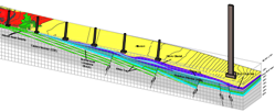
Fig 6 A ground model of the Southern Marine Area, showing upper and lower fluvio-glacial deposits, faulting and intrusions.

Fig 4 illustrates a ground model interpreted from preliminary studies and the GI findings from 2008 and 2009. The geology encountered was broadly as expected from the preliminary studies. However, the following key pieces of geological information did emerge from the five main areas of the site:

In the Southern Land Area, the Calders Member was found to consist of Port Neuk Sandstone, which is now known to extend beneath the main crossing’s south abutment and first viaduct pier, 500m further north than shown on the 1:50,000 geological map (Fig 3). Unlike other areas of the Forth Valley7, fluvioglacial deposits in Southern and Northern Marine Areas occur at two distinct levels of variable extent: an upper deposit resting on glacial till, and a lower deposit, below the till, resting on bedrock. The upper deposits are thought to represent sands and gravels of meltwater outwash terraces deposited during the retreat of the Highland Ice Sheet. The lower are thought to be the remnant of a previous glacial event.

The alkali dolerite sill, cropping out on the southern shore, extends beneath the Southern Marine Area as a series of sills rather than the single continuous dolerite mass encountered on land. These sills thin northwards such that very little dolerite was encountered beneath the South Tower location. These multiple thin dolerite intrusions possibly represent the advancing (finger-like) sill-front.

In places, the alkali dolerite has been significantly altered into an aggregate of calcium, magnesium and iron carbonates with kaolin and muscovite - referred to in the published literature as ‘white trap’. The alteration probably occurs through interaction of the magma with hydrocarbon-rich volatiles distilled from oil shales, carbonaceous mudstones or coals during intrusion. This type of alteration is most pronounced where dolerite sills are thin.

As part of a collaboration instigated by the JAJV, several cores were sent to BGS in Edinburgh to aid in the correct identification of strata. The core from the Central Marine Area penetrated through the quartz-dolerite intrusion into underlying sedimentary rock, which was expected to be the West Lothian Oil Shale Formation. However BGS identified it as the Sandy Craig Formation, which is now known to extend below the central tower at least 500m further south than shown on the 1:50,000 geological map (Fig 3). The sedimentary units of the Sandy Craig Formation encountered in the Central and Northern Marine areas do not appear to be from the same horizon; though whether higher or lower in the stratigraphy is not clear.

Fig 7
Fig 7 A ground model of the Central Marine Area, showing the Sandy Craig Formation (light brown) below the quartz-dolerite sill.

The Sandy Craig Formation at the North Tower is intruded by a dolerite sill at approximately 70mOD. BGS interpreted this as belonging to the same Namurian suite of intrusions encountered in the Southern Land and Southern Marine Areas. These sills have been assigned to a suite that is generally termed 'alkaline', however this is a very broad grouping and the suite is known to contain some sills that are slightly silica-oversaturated. Petrographic analysis by BGS has identified this as one such sill. BGS were also able to tell, from their complex contact relationships with the country rock, that these sills were intruded before the sediments were fully lithified. This fact, combined with the degree of alteration, suggested to BGS that the quartz-dolerite sill was a significantly younger intrusion that, at the time of emplacement, encountered a fully lithified sedimentary rock with significantly lower volatile content.

There were other surprises. In addition to the volcaniclastics expected within the Sandy Craig Formation, a volcanic neck and associated neck agglomerate were also tentatively identified in one borehole between the North Tower and the first north pier. And although, on the basis of the 1:50,000 geological map (Fig 2) and the 2008 and 2009 investigations, we expected to encounter bedrock at or near the surface across the entire area, the late glacial (“100ft”) raised beach deposit was encountered at approximately +22mOD during Ground Investigations in 2010.

GI information has generally supported the published suggestion that the Calders and Hopetoun Members dip at approximately 10 degrees NNE in the Southern Marine Area. However, the sedimentary strata beneath the quartz-dolerite exposure of Beamer Rock have tentatively been identified as displaying evidence for a shallow SE dip. The Sandy Craig Formation in the Northern Marine Area suggests a NE, which agrees with the Solid 1:50,000 geological map. In general, the unnamed major faults beneath the alignment (1:50,000 geological map) were not encountered during ground investigations. However, several minor faults were encountered that are almost certainly related. If these indicatively identified major faults exist, they probably lie beneath the navigation channels.

Fig 8 Fig 8 A ground model of Northern Marine and Northern Land Areas, showing upper and lower fluvio-glacial deposits and a volcanic vent.

CONCLUSION


These ground investigations revealed important information about the geological history of the area, including the process of sill emplacement, the increase in the geographical extent of the Sandy Craig Formation to beneath Beamer Rock, and the possible presence of a volcanic vent. From the geological and geotechnical information gained from these investigations, the Jacobs Arup Joint Venture developed the specimen design for the main crossing, the third generation of iconic bridge engineering to cross the Firth of Forth.

Acknowledgements


The authors thank Paul Mellon (Transport Scotland) for permission to write this article; Paul Mellon (Transport Scotland), Tom Casey, Alistair Chisholm, Adrian Collings, Anna Morley, and Paul Morrison (Arup), Paul Dunlop & Darren O’Mahony (Glovers Site Investigation), and in particular Mike Browne and David Stephenson (BGS, Edinburgh) for their contributions. The authors accept any residual errors or omissions in this article are theirs.

References

  1. Transport Scotland Forth Replacement Crossing [Online] Available from: www.transportscotland.gov.uk/road/projects/forth-replacement-crossing/ [Accessed 7th Feb 2011]
  2. Forth Bridges Visitor Centre Trust Before the Bridges, The Rail bridge and The Road Bridge [Online] Available from: www.forthbridges.org.uk [Accessed 7 Feb 2011]
  3. Forth Road Bridge History Timeline [Online] Available from: www.forthroadbridge.org/history/ [Accessed 7 Feb 2011]
  4. BGS (1985) The Midland Valley of Scotland, 3rd Edition, I B Cameron and D Stephenson
  5. BGS (2006) Sheet 32W Livingston, Bedrock, 1:50,000 scale
  6. BGS (1967) Sheet 32W, Livingston, Bedrock and Drift, 1:50,000 scale
  7. BGS (1986) Engineering Geology of the upper Forth Estuary, Report Vol 16, No 8, T P Gostelow and M A E Browne
  8. Pers comm , Stephenson, 2011

 * Arup