Product has been added to the basket
Articles

Bruce Yardley appointed Chief Geologist

Bruce Yardley (Leeds University) has been appointed Chief Geologist by The Radioactive Waste Management Directorate (RWMD) of the Nuclear Decommissioning Authority (NDA).

Chartership news

Chartership Officer Bill Gaskarth reports on a projected new logo for use by CGeols, advice on applications and company training schemes

Climate Change Statement Addendum

The Society has published an addendum to 'Climate Change: Evidence from the Geological Record' (November 2010) taking account of new research

Cracking up in Lincolnshire

Oliver Pritchard, Stephen Hallett, and Timothy Farewell consider the role of soil science in maintaining the British 'evolved road'

Critical metals

Kathryn Goodenough* on a Society-sponsored hunt for the rare metals that underpin new technologies

Déja vu all over again

As Nina Morgan Discovers, the debate over HS2 is nothing new...

Done proud

Ted Nield hails the new refurbished Council Room as evidence that the Society is growing up

Earth Science Week 2014

Fellows - renew, vote for Council, and volunteer for Earth Science Week 2014!  Also - who is honoured in the Society's Awards and Medals 2014.

Fookes celebrated

Peter Fookes (Imperial College, London) celebrated at Society event in honour of Engineering Group Working Parties and their reports

Geology - poor relation?

When are University Earth Science departments going to shed their outmoded obsession with maths, physics and chemistry?

Nancy Tupholme

Nancy Tupholme, Librarian of the Society and the Royal Society, has died, reports Wendy Cawthorne.

Power, splendour and high camp

Ted Nield reviews the refurbishment of the Council Room, Burlington House

The Sir Archibald Geikie Archive at Haslemere Educational Museum

You can help the Haslemere Educational Museum to identify subjects in Sir Archibald Geikie's amazing field notebook sketches, writes John Betterton.

Top bananas

Who are the top 100 UK practising scientists?  The Science Council knows...

Crossrail - the engineering geology

The Crossrail project is changing the face of London’s geology, says Ursula Lawrence*

Geoscientist 22.06 July 2012

The Crossrail project is a new underground railway through the heart of London. It will connect with 110km of new or upgraded sections of surface rail to Maidenhead, Shenfield and Abbey Wood. These upgrade and construction works are being delivered, on behalf of Crossrail, by Network Rail. The central tunnelled section comprises 21 kilometres of twin-bore, 7.2m-diameter tunnels, 11km of Sprayed Concrete Lined (SCL) tunnels at five new underground stations, cross-passages and crossovers, three new box stations, and a refurbished Victorian railway tunnel.

Trains from the Great Western Railway will run underground at Royal Oak, west of Paddington and pass through new stations at Paddington, Bond Street, Tottenham Court Road, Farringdon, Liverpool Street and Whitechapel. At Stepney Green a crossover cavern will be constructed, allowing the route to split.

Trains heading south east will pass through a new station at Canary Wharf to emerge at Victoria Dock Portal in docklands and allowing trains to call at Custom House for the Excel exhibition centre. The former North London Line has been reused, and the 140 year old cut-and-cover Connaught Tunnel refurbished. Trains will cross under the River Thames at North Woolwich to pass through the new station at Woolwich Arsenal before emerging at Plumstead on to the North Kent Line and terminating at Abbey Wood. 

Trains heading north east from Stepney Green will emerge at Pudding Mill Lane onto the Great Eastern railway, the first stop being Stratford and the last Shenfield, Essex. In addition to the nine stations and five portals, Crossrail includes five permanent shafts for ventilation, maintenance and emergency access. 


15207

 RUNNING TUNNELS


The running tunnels will be formed by eight closed-face tunnel boring machines (TBMs). Six of these will be earth pressure balance machines (EPBMs), which will be used for most tunnels. EPBMs are closed-face TBMs specially designed to cope with soft ground conditions with loose sedimentary deposits, large boulders, and a high water table. The other two will be Slurry Shield TBMs, which can cope with variable soft ground with high ground water flows, and will be used for the Thames Tunnel between Plumstead and North Woolwich.

Image: Royal Oak portal, ready to receive the Tunnel Boring Machine.

Tunneling began in May 2012 from Royal Oak portal with two TBMs (Phyllis and Ada) tunnelling towards the eastern end of Farringdon Station. Passengers travelling west out of Paddington will have seen the TBMs being prepared, under the flyover. Three of the TBMs are due to set out from a new shaft at Limmo. Two (Victoria and Elizabeth) will head west to Farringdon, while the third will head east to Victoria Dock portal. It will then be dismantled and brought back to Limmo to construct the second tunnel to Victoria Dock. Another TBM will set out from Pudding Mill Lane and tunnel to the Stepney Green crossover cavern. There it will be dismantled and removed via the shaft, to return to Pudding Mill Lane to bore the second tunnel. The last two TBMs (Mary and Sophia) will set off from Plumstead and tunnel to North Woolwich. Most of the underground structures are due to be completed by 2015, when systems fit out will begin.


F1 Cartoon

Above :  Simplified geology section of the Crossrail Route.

F1 tunnel routeRoyal Oak Portal is constructed in the London Clay. The tunnels continue in the London Clay through Bond Street and Tottenham Court Road stations until Fisher Street Crossover, where the Soho anticline brings Palaeocene strata closer to surface and the tunnels enter Lambeth Group clays and sands.

Picture: The Crossrail route through London

Between Fisher Street, Stepney Green and Pudding Mill Lane, the tunnels mostly follow the boundary between the London Clay Formation and the Lambeth Group. South east of Stepney Green the tunnels descend through the Palaeocene sequence in to the Thanet Sand Formation as they cross the Millwall anticline - centred at Canary Wharf - before rising up to terminate in the London Clay at Victoria Dock portal. The portal lies on the eastern side of the Greenwich Syncline and recently discovered Plaistow graben. The route continues east through Silvertown, along the surface section that was the former North London Line and over the Greenwich Fault Zone.

North Woolwich portal is constructed through Alluvium overlying River Terrace Deposits and into the Chalk, which is here brought to surface by the Greenwich Anticline. The tunnel then continues mostly through Chalk to Plumstead portal, only rising into the Thanet Sand Formation at Woolwich Station.

The geology partly controls construction methodology, with the Sprayed Concrete Lining (SCL) methods being used in London Clay and Lambeth Group clays at station tunnels, shafts and cross passages. Bolted segment linings are to be used in cross passages in the Thanet Sand and the Chalk. Paddington and Woolwich box Stations are of ‘diaphragm wall’ construction - a reinforced concrete wall constructed in the ground by excavating a narrow trench that is kept full of bentonite slurry. However, Canary Wharf box station has been constructed with piled walls. This is because Canary Wharf sits in the middle of West India Dock, and three of the station walls are also the edges of a cofferdam and tie into existing retaining walls.

ACT OF PARLIAMENT


F1 tunellingStrategyThe scheme, which is financed by a mixture of private and public funding and required an Act of Parliament, was first proposed and began its passage through Parliament between 1989 and 1996,. The project was restarted in 2002 and extended to its current alignment.Over the last 10 years, 37 packages of ground investigation were carried out over the entire tunnelled route to form a geological model, obtain samples for derivation of engineering parameters and form a baseline of groundwater monitoring, including tidal monitoring Ground investigations, comprising 1043 boreholes with a total length of 34,341m, were completed in 2011. Third party data sources were accessed adding 653 boreholes (25,156m). The Crossrail ground model is built around almost 1700 boreholes representing c. 60km of ground and the database combining all ground investigation data contains well over a million lines of data and can be accessed easily and quickly.

The depths involved meant that ground investigations had to be based around deep boreholes, typically between 40m and 60m deep - although the deepest reached 114m. All boreholes were drilled off the tunnel route, to avoid forming pathways for water, and so that grouted boreholes could neither provide a flow-pathway nor collapse when encountered at depth - a particular risk in SCL sections. Deep boreholes carry risks, especially from jammed casing. In recent years all boreholes deeper than 30m were rotary cored to minimise these risks and improve safety for drilling teams. In addition to providing utilities drawings, specialist surveys were carried out to mark out utilities on the ground prior to drilling and flame retardant coveralls were mandated during inspection pit excavation.

Crossrail was careful to ensure a consistent approach to variations in stratigraphy along the route, identifying fault zones through detailed geological logging, as well as areas that were especially hard (nodules, concretions) or soft. We ran training courses for contractor staff, using geologists expert on the groups to be encountered. Particularly difficult sections with contemporaneous faulting were check-logged by the specialists themselves and confirmed numerous faults along the route. For the running tunnels, boreholes were drilled on average 100-150m apart depending upon obstructions and geological variation. Relatively homogenous deposits such as the London Clay were investigated at a slightly wider spacing whereas the more variable Lambeth Group was investigated at slightly closer spacing. Although the ideal spacing had to take account of local obstructions. Boreholes were drilled wherever a rig could be squeezed including car parks, parks, basements and tiny yards. Many times suitable sized areas were identified only to find that all the utility companies had got there first!


15607Image :  Crossrail will utilise some pre-existing tunnels

Crossrail is a major project beneath a historic and congested urban area. It was important that risks associated with ground conditions were identified, understood and managed throughout the design and construction stages of the project. The risks to the project come in two forms - stratigraphic risks arising from the geology and location risks due simply to working in London. Two main stratigraphic risks arise from obstructions and irregular groundwater flows. Several strata contained irregularly cemented horizons, nodules and concretions. Advanced knowledge of these is important for TBM design and for constructing excavations. The face of the TBM contains teeth and cutters and tend to get broken and worn by the Nodules and concretions which tend to be much stronger than the surrounding soil,. This slows down progress

The London Clay contains layers of septarian nodules, typically up to 150mm thick and up to 2m across. The Harwich Formation contains irregularly developed concretions. One, encountered in the Isle of Dogs (Blackheath Member), measured a metre in thickness and five metres by ten metres in plan - a significant obstruction. In a large excavation, it poses few problems as heavy machinery can be brought in. However in a small or deep excavation the situation is completely different and can lead to damaged equipment or very slow progress. The Lambeth Group presents another form of obstruction, namely water flows from sand channels. During the Palaeocene, these were channels - small streams to large rivers - crossing the tidal mudflats between mangrove swamps, especially in the east, where the environment was becoming shallow marine. Their sinuosity and variability make them very difficult to predict and locate. Trying to drill through one is like finding a needle in a haystack. These rapid lithological changes make resolving fault alignment even more difficult and this is where detailed logging to the latest stratigraphic nomenclature comes into its own.

We installed 1132 piezometers to provide detailed information on the pore pressure profile along the entire tunnelled route. Particular attention has been paid to monitoring groundwater in the sand channels. These are in continuity with the clays surrounding them, but the difference in permeability means that water influx can affect the stability of excavations. Again, this is more a problem for SCL construction than when using a closed face TBM. Pump testing has helped us design depressurisation systems for in-tunnel dewatering. Groundwater monitoring has been on going in a co-ordinated programme since the 1990s and restarted during the early 2000s. This growing dataset has been used to derive groundwater pressures on the structures before and during construction. Wider groundwater monitoring by the Environment Agency has been used in modelling for the 120-year design life of Crossrail structures.


F1 HarwichFmThe risks of simply being in London include faulting, obstructions and the presence of sensitive structures. Knowledge of faulting in London is changing with the ground investigations from large projects like Crossrail. In the 1990s when the route for Crossrail was first being planned, it was the route only crossed one major faulted area (Northern Boundary Fault). Crossrail has worked with BGS to produce a three-dimensional block model for Farringdon Station which indicated three main sets of faults with varying degrees of uncertainty. Additional phases of ground investigation have not only targeted and reduced these areas but also indicated additional faults in each set.

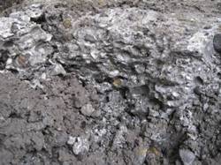
Image:  A concretion in the Harwich Formation

The detailed logging of borehole samples and cores has helped to define faults across the entire route. For example, an additional eight faults have been discovered in the Chalk alone! The recently discovered Plaistow Graben has now been extended south west to cross the Crossrail route near Isle of Dogs. Knowing where faults lie is important for two reasons. First, ground conditions can change across a fault. This is particularly important for SCL construction, as changes from clay to sand, especially water bearing sand, can affect excavation stability, the potential for base heave and dewatering requirements.

Second, faulting rarely occurs as a single plane; more usually it is a series of fractures that breaks up the ground and creates voids, resulting in an increase in secondary permeability decreased excavation stability and greater transmission of ground movements. The fault zone can form a preferential path for groundwater flow along it or form a barrier to water flow across it. These flows can have a significant influence on the development and performance of dewatering schemes, potentially leading to differential settlement across fault zones or additional dewatering requirements. Also, the broken ground contains sheared blocks that can fall into excavations. Not only does this cause over-break, but it is a potential safety hazard for the workforce. It has been a feature of excavations in London Clay with miners traditionally referring to the blocks as greasy backs

London has a long history which records much of our technological development. Hydraulic and pneumatic power networks for lift rams, wells and all kinds of deep foundations remain in the ground even when the original aboveground structure has long gone. A team of people have scoured numerous public and private archives to collect the available information, confirm the nature of any clashes and provide any mitigation measures. Records of these obstructions can vary from detailed to non existent, including duplicated and erroneous data. Safeguarding procedures through council planning applications reduces the risk of clashes with very recent developments.


FI 3D block model

GROUND MOVEMENT


Image : A three dimensional block model as supplied by the British Geological Survey, showing boreholes and formations of interest

Tunnelling causes ground movement at the surface because the face of the TBM is slightly bigger than both the shield behind it and the segmented tunnel lining constructed behind that. Ideally, the ground pressures are balanced across the face of the TBM so that the face does not relax or move significantly. The space behind the face and around the shield is filled with grout as soon as the segments are placed, but the ground does move a small amount, typically around 1.5% of the area of the TBM face. The movement is transmitted to the surface and, typically, results in a broad and shallow settlement trough – c. 30m across and c. 25mm deep at the centre.

The Crossrail route crosses under some 474 listed buildings, of which eight are Grade 1, myriad utilities including major sewers and much of London’s transport infrastructure (Underground, roads and canals). Settlement assessments have been carried out on each, within the settlement trough, to determine the movements that could arise, using industry recognised procedures and software. Buildings and all infrastructure are instrumented, subject to a co-ordinated monitoring regime and mitigation measures implemented where necessary. Detailed knowledge of ground conditions feeds directly into the settlement assessments, as the movements are calculated to be small but also because many of the structures assessed are fragile.

The Crossrail project has involved a huge effort, just to get to construction - involving ground investigation and baseline monitoring over many years. Improved understanding of the ground model has benefited the project’s ability to calculate ground movements, plan mitigation measures and has contributed enormously to our understanding of London’s geology.

* EurGeol Ursula Lawrence CGeol CSci FGS is an engineering geologist working for Crossrail.  She also acts as a scrutineer and mentor on the Society's chartership scheme.